
Key Takeaways at a Glance
Storage control and routing for container conveyor systems answer the same question: where should the handling unit go next? This article covers the basic mechanics, configuration, practical sequences, and limits of both logics, and explains what the choice in the blueprint should be based on.
The interface decides, not the conveyed goods
Which routing logic fits follows from the telegram interface and the division of tasks between EWM and the PLC, not from pallet or container.
Chain of legs or direction decision
LOLS builds the path leg by leg via warehouse tasks, while BFT routing decides purely by reading at every reporting point.

Both approaches have clear limits
Alternative routes and true pathfinding have to be developed yourself in both cases, but thanks to the default, the BFT logic always returns an answer.
1. Introduction
Layout-oriented storage control came first. It was used mainly for pallet conveyor systems; for container systems there was simply no suitable solution. Routing for container conveyor systems came later.
This sequence gave rise to the names, and with them to a persistent misunderstanding. BFT routing does not only work for container systems; it can just as well be run on a pallet conveyor system. Which logic ends up being used depends on how the system is designed and implemented, and not on what is lying on the conveyor.
The decisive factor is the division of tasks between EWM and the programmable logic controller. How fine-grained does EWM decide, and how much pathfinding do you leave to the system?
The choice of a routing logic should therefore not be made based on the conveyed goods, but based on the telegram interface, the reporting point logic, and the question of where the pathfinding should take place.
In the following, we go through both routing logics: basic mechanics, configuration, and the points where the standard no longer helps.
You can find an overview of controlling automated warehouse equipment directly from SAP EWM on our service page SAP EWM Material Flow Control.
It is not the load carrier that decides the routing logic, but the design and implementation of the system.
Storage control requires the PLC to understand a reporting point as a destination. BFT routing is more flexible: there, the logical destination can be a direction or, likewise, the next reporting point.

2. Technical Fundamentals
Both approaches answer the same question: where should the handling unit go next? The way they arrive at the answer, however, differs considerably.
Same building blocks, completely different logic
Both variants are based on reporting points and mostly work with the same objects: reporting points, conveyor segments, PLC definition, telegram processing.
The only difference is the routing logic on top.
2.1 Layout-Oriented Storage Control (LOLS)
Layout-oriented storage control kicks in whenever a movement cannot lead directly from the source bin to the destination bin, but has to pass through an intermediate bin. A classic example: a pallet is to go into the high-bay rack. First, however, the contour and weight check at the identification point is due, then it moves to the handover point for the storage and retrieval machine, and only from there to the actual storage bin in the high-bay rack.
The mechanics behind this is a chain:
- The warehouse task to the actual destination (A → D) is created as inactive. The destination therefore remains known the whole time.
- In parallel, an open warehouse task to the next intermediate bin (A → B) is created.
- When B is confirmed, the source bin of the inactive warehouse task is changed from A to B and checked again: is there another intermediate bin from here? If so, the next open warehouse task (B → C) is created.
- If a direct movement to the destination is possible, the inactive warehouse task is activated and runs as the last leg.
The path is therefore not created up front, but leg by leg, each time the previous leg is confirmed. And one more restriction: LOLS does not work without handling units.
Behind an intermediate bin there is practically always a reporting point to which a bin is assigned. This does not yet say how far a leg reaches, though: the next intermediate destination does not have to be the next intersection or the reporting point after that. How big the jumps are depends on how much pathfinding is implemented in the controller.
There are options for alternatives, but only to a limited extent. Several intermediate bins can be maintained via the sequence number. If B is occupied, B1 can be found. However, this always applies only to the next step. C is checked at all only when C becomes the current next intermediate bin. The standard does not evaluate entire routes in advance.

This is maintained in two places in configuration, which lead to the same definition: under Material Flow System (MFS) → Storage Control or under Cross-Process Settings → Warehouse Task.
Relevant for project and configuration teams:
| Object | Type | Meaning |
|---|---|---|
| /SCWM/V_TROUTL | Maintenance view | Define layout-oriented storage control |
| /SCWM/TROUTL | Table | Source/destination combination → intermediate bin |
| /SCWM/TROUTLS | Table | Storage sections per storage type |
| /SCWM/DE_VLBER_LGST | Data element | Source storage section |
| /SCWM/TROUTL_DET | Function module | Read logic at runtime |
The structure of /SCWM/TROUTL explains the mechanics by itself: the selection uses source storage type and source storage section (VLTYP/VLBER) as well as destination storage type and destination storage section (NLTYP/NLBER) – in other words, from where and to where. The result is the next intermediate bin (ILTYP/ILBER/ILPLA). Alternatives can be stored via the sequence number (SEQNR). The table cannot represent a complete path; one record always describes just one step.
2.2 Routing for Container Conveyor Systems
For an HU, a container conveyor system usually knows only the barcode, and a decision has to be made immediately, because the container does not wait. So at every reporting point, the HU attributes are used to determine where it goes next. Left, right, straight ahead.
Three things are decisive here:
- Everything is read-only. The routing decision itself creates no warehouse task and changes no status.
- The HU moves from intersection to intersection. As a rule, only a direction is sent to the PLC.
- There is always an answer. Through the default record, the PLC receives a direction in every case, if necessary toward the clarification point.
The criterion is either the activity area, that is, the HU’s business destination, or its status in EWM: defective, empty, without order. If none of the maintained records matches, the default value applies.
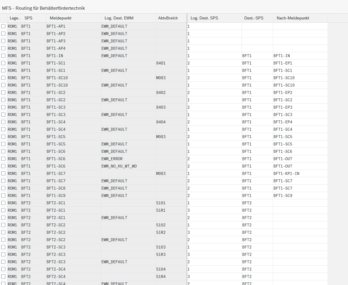
Technically, the routing consists of three building blocks that work together as a translation layer. EWM thinks in statuses, while the PLC only knows outputs.
Relevant for project and configuration teams:
| Object | Type | Meaning |
|---|---|---|
| /SCWM/TMFSLD_E | Table | Logical destinations EWM – business statuses of the HU |
| /SCWM/TMFSROUTE | Table | Routing definition: reporting point + criterion → direction |
| /SCWM/TMFSLD_P | Table | Logical destinations PLC – physical outputs |
| /SCWM/MFSACT_CASE_ROUTE | Function module | Routing decision at runtime |
The actual routing definition in /SCWM/TMFSROUTE combines PLC and reporting point (PLC/CP) with the selection criterion (LD_EWM or AAREA) and returns the direction (LD_PLC). Optionally, a destination reporting point to which the HU is posted can be maintained. The movement posting then takes place either asynchronously or based on the actual routing that the PLC reports back to EWM.
Where the activity area comes from is left open: it can come from the rough bin determination, but just as well from an existing product or HU warehouse task. This does not matter for the routing decision; only the result is read.
Unlike LOLS, the table has no sequence number field. Alternative routes for locked or blocked reporting points therefore cannot be stored in the standard at all.
2.3 The Real Distinguishing Criterion
Instead of “pallets here, containers there,” the division of tasks is a much better fit:
The shortest rule of thumb
The more logic sits in the controller, the better storage control fits – provided the PLC understands a reporting point as a destination and finds the intermediate paths itself.
The less the PLC can do, the better BFT routing fits, because EWM then has to decide at every branch itself.
BFT routing can do both: as a logical destination, you can store a direction, but just as well the next reporting point.
| Routing for container conveyor systems | Layout-oriented storage control | |
|---|---|---|
| Decision density | At every intersection | Only at relevant leg points |
| Reach per decision | Up to the next intersection | Up to the next leg destination (A → D) |
| PLC’s own share | Minimal, only goes where told | High, finds intermediate paths itself |
| Content of the destination | Direction or next reporting point | Reporting point / intermediate bin only |
| Data impact | Read-only | Write (create and activate WT) |
| Placing load carriers on the conveyor | Possible practically anywhere | Only at defined points |
2.4 Configuration at a Glance
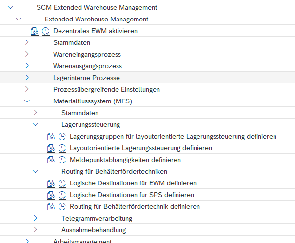
In the SPRO tree, both logics sit under the same node, but in separate branches.


3. Putaway into the Automated Warehouse: Why Late Decisions Work
One special case deserves its own chapter because it goes beyond the basics: how the container conveyor system works when putting away into the automated small parts warehouse.
If putaway into an automated warehouse takes place via the container conveyor system, the logic can already perform a rough bin determination in the standard, and it is allowed to run asynchronously. The process decouples movement and decision:
- Scan at the I-point: the HU is identified and moves on immediately.
- The rough bin determination runs in the background. The system does not wait.
- At the next scanner, the HU is routed up to the aisle based on the rough result.
- Only immediately before the storage and retrieval machine is the specific destination determined and a warehouse task created for the resource.
Decisions are therefore made as late as possible and, at first, only as precisely as necessary. With LOLS it is the other way around: there, the destination is in the inactive warehouse task from the start. A system that waits for the complete bin determination on every putaway cannot keep up at container speed.
Important exception
Resources always need a warehouse task – regardless of whether BFT routing or storage control is in use.
On the conveyor line, the two worlds differ fundamentally. At the resource, they converge again.
Not every vehicle has to be a resource, however: if the PLC optimizes a vehicle through its own order buffer – a shuttle car, for example – it is enough to define the reporting points it serves.
4. Architecture Decisions: What Needs to Be Clarified in the Blueprint
The most important decision is made in the business blueprint, when the telegram interface is coordinated with the system integrator. This is where it becomes clear what the controller expects as a destination and how much pathfinding it handles itself. The suitable routing logic follows from this.
The trap lies in the term itself. Just because you are talking about a pallet system does not mean it has to be storage control. If you base the decision on the word “container conveyor system” instead of the interface, you quickly end up with the wrong variant and only notice once the configuration is done.
4.1 With BFT, Performance Is an Architecture Topic
In container conveyor systems, the response time to a routing request is the central constraint. The container stands at the intersection waiting for a direction; any delay immediately affects throughput.
This results in a few hard rules for enhancements:
- High-performance coding belongs in the routing path. No highly complex algorithms, no sprawling determinations.
- No postings in the routing itself. Anything that writes extends the response time.
- Run complex determinations and postings asynchronously where possible, as the rough bin determination from chapter 3 demonstrates.
As a rule of thumb for custom enhancements: anything in the routing BAdI that is not processed within a few milliseconds does not belong there.
4.2 Queue or Direct Send – a Fundamental Difference
An architectural difference that is hardly visible in configuration concerns the telegram’s path to the PLC. With storage control, every warehouse task that is to go to the controller first lands in a PLC-relevant queue. This queue is read, and only then does the warehouse task go out.
This intermediate step has a practical benefit. Before sending, you can check whether the next reporting point or the next conveyor segment still has capacity to take the HU at all. If not, the warehouse task simply stays in the queue. The pallet is not even sent off. The same happens when the PLC reports a fault on a conveyor.
Capacity limits can be placed on reporting points, conveyor segments, or resources. Incidentally, you only have to define conveyor segments if you want to manage their status and capacity in EWM. Often it is enough to maintain both at the reporting points.
Container conveyor systems do not have this intermediate stage. In the standard, only the direction is determined, the response telegram is created directly in the coding and sent immediately. No buffer, no upstream capacity check, no way to hold back a request.
What this means in practice
With storage control, congestion can be avoided before it occurs, because the capacity check takes effect before the HU starts moving.
With BFT, the HU sets off and, if necessary, is redirected via the default. Congestion cannot be prevented this way, but the HU drives past it.
4.3 Sizing Telegram Processing Correctly
Back to performance, this time from the infrastructure perspective. On a running system, several reporting points send requests at the same time, and they do so continuously, not just at peaks.
- Allow several parallel processes for telegram processing. A single process becomes a bottleneck as soon as several reporting points send requests at the same time.
- Design telegram processing for a separate application server so that enough processes are permanently available and dialog operation does not interfere.
- Decouple status telegrams from routing: several channels per PLC, for example one for routing requests and one for status messages.
The channel separation is often overlooked. Depending on the size of the system, a great many routing requests come in, and each one blocks a container. Status messages, by contrast, are far less frequent and not time-critical; they do not have to be processed within the telegram sequence at all. If everything still runs over the same channel, a single status message can slow down the routing requests waiting behind it.
How to monitor telegram communication in operation and narrow down faults is described in our article “Telegram Monitoring in SAP EWM MFS: Retry, CP Channels, Queue Backlogs and Practical Debugging”.
4.4 Other Pitfalls
Another point is the placement of the reporting points. First, in configuration: actions that create, change, or confirm warehouse tasks should not be triggered at reporting points that are close together – otherwise lock conflicts in WT processing are a risk.
Second, quite physically on the system: if two reporting points are too close together, there is too little time between the two requests. In configuration this looks clean; it only becomes a problem at runtime.
5. Practical Comparison: The Same Process with Two Routing Logics
5.1 Return to Storage with LOLS
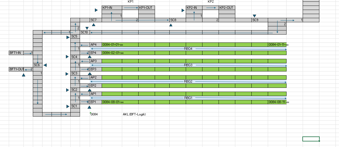
Let’s take the pallet layout from chapter 2. At picking station 1, the removal is finished, and the partially used pallet is to go back into the rack, specifically into aisle 3 to storage bin 0083-05-04-03. This is not possible directly; between KP1-OUT and the aisle there are two reporting points and the putaway point.
This is how layout-oriented storage control works its way through:
| Leg | Confirmation at | LOLS finds | Result |
|---|---|---|---|
| Start | — | Intermediate bin CP1 | Inactive WT KP1-OUT → 0083-05-04-03 plus open WT KP1-OUT → CP1 |
| 1 | CP1 | Intermediate bin CP2 | New open WT CP1 → CP2 |
| 2 | CP2 | Intermediate bin EP3 | New open WT CP2 → EP3 |
| 3 | EP3 | No further intermediate bin | The inactive WT is activated: EP3 → 0083-05-04-03 |
A continuous route description never exists at any point. The destination is in the inactive warehouse task from the start, but the path to it only emerges gradually, each time the previous leg is confirmed. If the check returns no further intermediate bin, the inactive warehouse task is activated and takes over the rest.
The storage and retrieval machine drives the last leg from EP3 to the storage bin. This applies the rule from chapter 3 that, regardless of the routing logic on the conveyor line, resources always need a warehouse task.
Why the storage section makes the difference here
At CP2, a decision has to be made on whether to go to EP1, EP2, EP3, or EP4. The destination storage type 0083 alone cannot answer this question – it is the same for all four aisles.
That is what the storage section (/SCWM/TROUTLS) is for. It subdivides the storage type far enough for layout-oriented storage control to head for the right aisle.
If one of the four records is missing in configuration, for example the one from CP2 toward aisle 3, the check finds nothing. There is no default value that steps in. Instead, the inactive warehouse task is activated, and the PLC receives a telegram with a destination it cannot reach from this position.
5.2 When the Putaway Point Is Occupied
It gets more interesting when something gets in the way. The HU is on its way on the open warehouse task CP2 → EP3, but EP3 is currently occupied. It cannot be set down there, so it drives past and continues its lap in the loop.
What happens in EWM in the meantime:
- The HU reports back at the next known reporting point – here CP1.
- The open warehouse task CP2 → EP3 is confirmed with the exception code CHBD. CHBD stands for Change Destination Bin and allows the destination bin to be changed during confirmation – so the posting goes to CP1 instead of EP3.
- The destination 0083-05-04-03 in the inactive warehouse task is retained, and its source bin moves along to CP1.
- With the confirmation, layout-oriented storage control is evaluated again – this time starting from CP1. And there is an entry toward aisle 3 via CP2.
- A new open warehouse task CP1 → CP2 is created, and the chain of legs runs a second time.
The HU therefore does a lap and tries again for as long as EP3 stays occupied. This is not elegant, but it works, because the loop inevitably leads the HU past a position that is maintained as a source position in layout-oriented storage control.
The price of this rescue loop
Every position where an HU can end up unplanned must be maintained as a source position in LOLS – otherwise the chain ends there.
With a clean loop, this is manageable, because only a few reporting points come into question anyway.
With branched layouts, the maintenance effort grows quickly, and the gaps rarely show up in test operation.
In container conveyor systems, this case would not arise at all, because a new decision is made at every reporting point anyway, without prior confirmation. An occupied putaway point would be just a direction decision that turns out differently this time.
5.3 The Same Path with BFT Routing
The same task in the ASPW layout: an HU comes in and is to go to aisle 3. There is no chain of legs here, and not a single warehouse task along the way.
At the infeed point BFT1-IN, the HU is scanned and the contour is checked; at the same time, the rough bin determination starts. The HU does not wait for the result, however; it sets off right away, toward direction 1.
| Reporting point | What is checked | Direction | Consequence |
|---|---|---|---|
| BFT1-IN | Scan and contour check, rough bin determination is triggered | 1 | HU moves on, the determination runs in the background |
| SC6 | Is a rough bin determination available by now? | 1 / Default 2 | Yes: on into the loop. No: outfeed via BFT1-OUT |
| SC1 | Target activity area = aisle 1? | 2 / Default 1 | No: straight ahead |
| SC2 | Target activity area = aisle 2? | 2 / Default 1 | No: straight ahead |
| SC3 | Target activity area = aisle 3? | 2 | Direction 2 is maintained for this reporting point and this activity area – the HU turns off |
| EP3 | Scan of the HU | — | Only here is the final storage bin determined and a warehouse task created for the S&R machine |
Up to EP3, everything was read-only: no confirming, no exception code, no inactive warehouse task in the background. The warehouse task is created only where it is strictly needed, namely for the storage and retrieval machine.
The role of the default is also easy to see. At SC6, it catches the case where the rough bin determination is not yet finished or was not possible at all; the HU is then discharged again. At SC1 and SC2, default means little more than “not my aisle, keep going.”
5.4 Full Putaway Lane with BFT
If the lane to EP3 is occupied, the PLC continues straight ahead anyway, depending on its programming. The HU then does its lap in the loop via default routing and tries again on the next pass at SC3, until the putaway lane is free.
No error, no intervention, no stuck warehouse task. The HU stays in motion, and at some point it works.
The flip side: at some point it has to stop
The HU does not stop circling on its own. A loop counter that discharges the HU or triggers a message after n laps is not provided in the standard and has to be developed yourself.
Without this custom development, an HU may keep going indefinitely – inconspicuous in operation, but unfortunate for throughput and analysis.
Compared to chapter 5.2: with LOLS, the deviating position had to be posted and the chain set up again. With BFT, nothing special happens in EWM. The HU comes by again, is read, and the decision is made again.
6. Limits: What Neither Approach Delivers
Both approaches hit the same limit, if for different reasons: they are decision mechanics, not pathfinding. If you need genuine route optimization or an evasion logic for faults, you have to develop it yourself in both cases, just in different places.
6.1 What LOLS Cannot Do
- No evaluation of entire paths. Only the next step is ever considered.
- Alternatives via the sequence number work only locally, never across several legs.
- No default. What is not maintained does not exist.
The last point in particular has consequences. If a path is missing in configuration, the inactive warehouse task is usually activated and a telegram with an unreachable destination is sent to the PLC. Operationally, this is more unpleasant than a clean abort, because the error only becomes visible on the system and not in EWM.
Deviating postings are possible via the exception code CHBD – but then every path that could go wrong must also be captured in layout-oriented storage control. This scales poorly and rarely shows up in test operation.
6.2 What BFT Cannot Do
- Alternative routes for blocked or locked reporting points are not provided in the standard.
- The configuration is relatively rigid; complex pathfinding would have to be developed.
- EWM does not know the topology behind a direction and therefore cannot evade at all.
6.3 A Weakness That Becomes a Strength
What denies BFT the alternative route makes it robust in operation. Because a default record exists at every reporting point, the PLC always gets an answer. A container never stops; if in doubt, it heads toward the clarification point and thereby clears itself out of the system. With LOLS, by contrast, the pallet stays put if the matching record is missing.
7. Conclusion: The Interface Decides, Not the Load Carrier
Storage control and container conveyor systems describe less the load carrier than the question of how much of the decision lies in EWM and how much in the system.
LOLS builds a chain of warehouse tasks via intermediate bins. The destination is fixed early, traceability is high, and so is the maintenance effort. Without a matching configuration record, however, there is no plan B. The BFT logic decides in small steps, telegram-driven and purely by reading, at every intersection. Good for throughput, but without an alternative route.
For project practice, this means: the decision for one of the two logics is not made in the EWM blueprint; it follows from the interface to the controller. If you clarify this early, you spare yourself a rebuild project later.
The project rule in one sentence
If you do not clarify in the blueprint whether the PLC expects a destination or only a direction, you are not deciding on a configuration detail, but on the entire MFS architecture.
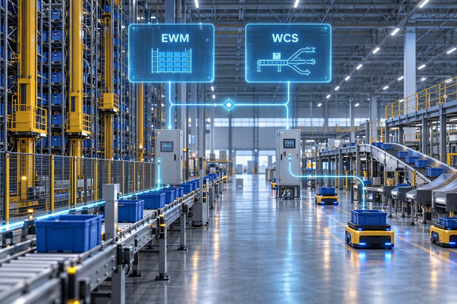
When SAP EWM MFS makes sense overall and when an external material flow controller is a better fit is shown in our article “SAP EWM MFS vs. WCS: When SAP EWM MFS Makes Sense – Architecture, Limits & Practical Experience”.
Frequently Asked Questions About LOLS and BFT Routing
Answers to typical questions from blueprint, configuration, and operations on choosing between layout-oriented storage control and routing for container conveyor systems in SAP EWM MFS.
Yes. What matters is what the PLC expects in the telegram and how much pathfinding it handles itself. With a controller that needs a direction from intersection to intersection, BFT routing also fits pallets.
Because layout-oriented storage control has no default. If the matching record is missing, there is no detour. The container logic always has a default value and, if necessary, sends the HU to the clarification point.
Not necessarily on the conveyor line – the routing decision is purely read-only. At resources such as storage and retrieval machines, however, a warehouse task is always required, regardless of the logic chosen.
Because only storage control can check in advance whether the next reporting point or conveyor segment has capacity at all. The queue is the tool for this: if capacity is insufficient, the warehouse task simply stays put. BFT has no such intermediate stage; it sends directly.
The HU does not have to wait for the final destination to set off. This keeps the system fast, because the complex determination runs in the background while the HU is already on its way.
For two reasons. In configuration, lock conflicts are a risk if several WT actions are triggered too closely together. Physically on the system, there is simply too little time between two requests for the response to still arrive on time.